New 3 Wheeler Model
Jigs
Zero clearance table saw insert
Remove the insert from your table saw. If there is a lip all around the hole to support the insert you can make one like mine.
Put the saw's insert, inverted, on the 3/8" plywood and mark its outline. Cut the outline on a band saw.
Unplug the table saw and remove its blade. Vacuum out the under side of the saw, or prepare to eat dust. Set the plywood piece in the insert location and put something heavy on it to hold it in place. Slide in under the saw with a pencil and mark the edge of the insert hole's lip on the plywood. Also mark the hole(s) for the hold down screw(s). Afterwards, line up the original insert on the bottom of the plywood and mark the outline of the blade slot.
Measure the depth from table surface to the lip. Pick a straight router bit and adjust the router depth to leave the plywood the thickness you just measured from the table saw. Remove the material where the plywood will rest on the lip. Then cut the blade slot area to the same depth. This should give you a piece that when you put it in the insert hole on the saw, its top fits flush with the table saw's top. Touch up the router work as needed.
Drill the hole(s) for the screw(s) and countersink the top side.
To use it I installed a 7 1/4" 60 tooth 'Ultra Fine Tooth' blade to get as clean a cut as possible on the narrow spoke strips. With the blade lowered, screw down the plywood insert then position the fence on the insert close to the blade but not directly over it to clamp the insert down. Start the table saw and slowly raise the blade, cutting through the plywood, until it has come up high enough to cut through the board you are using for the spokes. Raise it a slight bit more, then back it off, to keep the blade from constantly rubbing on the ends of the slot it has cut.
Spoke making jig:
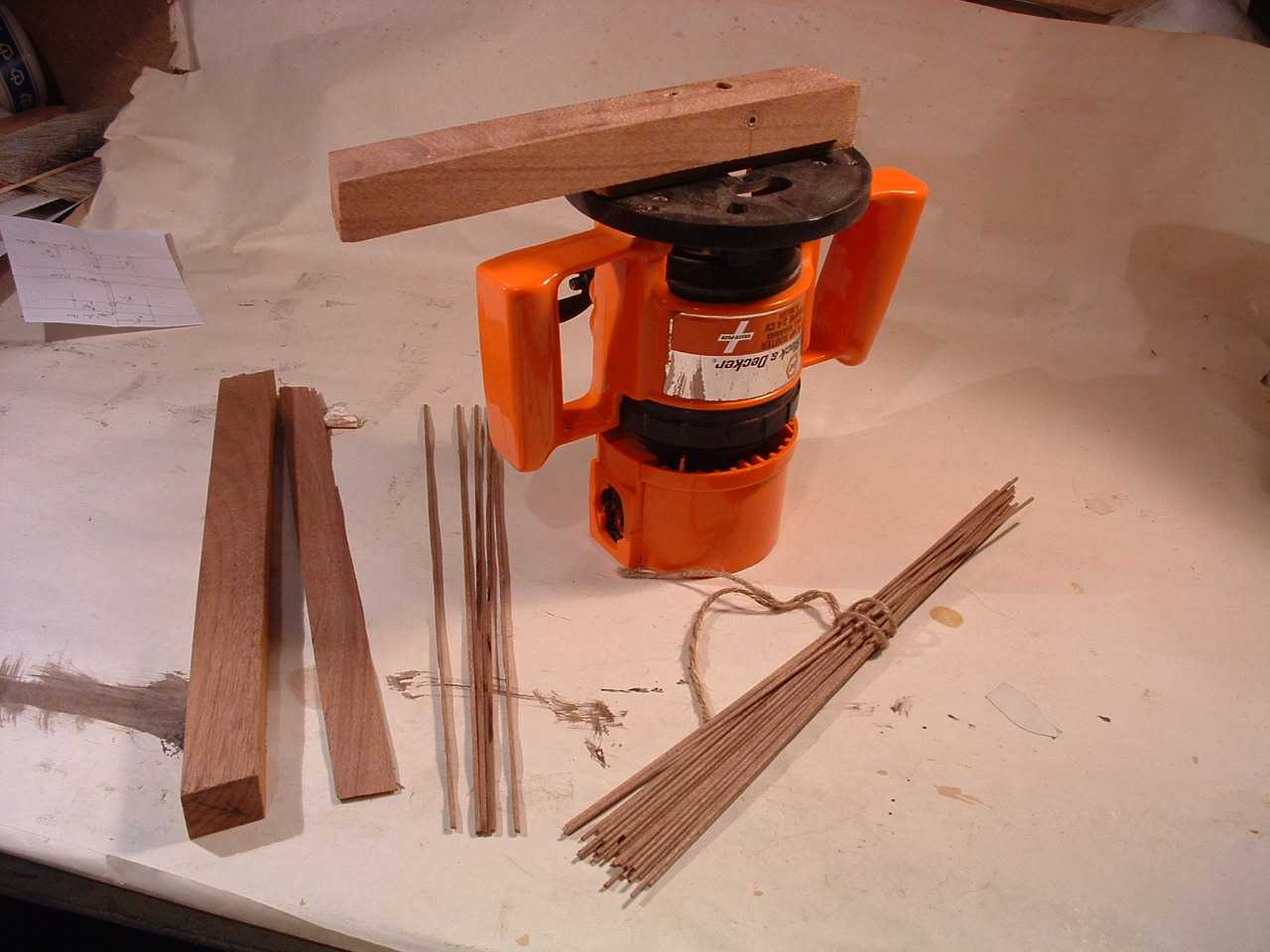
The jig is the unit screwed onto the router's base plate. It has a 5/64" hole drilled through the wood widened to 7/64" half way through. A 1/8" hole is drilled through perpendicular to the first hole located just before where the first hole narrows. Then that hole is widened to 5/16", going deep enough to let the 1/8" router bit reach into the 5/64" hole. I widened the opposite end of this hole as well, to let the saw dust escape easily. Your drill's chuck needs to clear the router base plate when you feed the sticks into the 7/64" hole, I had to add a spacer. To set the router bit depth, you want to just see the tip of the bit moving across the side of the 5/64" hole when you hand rotate the chuck while looking through the 5/64" hole. Then back it out a tiny bit.
In use you clamp the board to the bench top, router up. Fix one of the square sticks into the chuck of an electric drill. Set the end of the stick in the 7/64" end of the hole, start the router, start the electric drill and gently press into the jig. If it will not go through the 5/64" end of the hole pull out the stick, shut of the drill and router and feed the router bit in a little further. When it first goes through the exit hole stop everything and measure it with vernier callipers, adjust router as needed. When you have fed a stick in as far as the drill will go, shut off the router and drill and pull the dowel out. After doing this on each stick switch the drill to run in reverse. Then push a stick into the jig, fix the far end in the drill, start drill and router and pull the stick the rest of the way through.
Spoke hole drilling jig:
The design criteria for this jig are:
- The spokes all have the same tilt relative to the plane of the wheel, 22 degrees.
- The lines the spokes follow pass 7 mm. or 0.276" to either side of the axle centre.
- The spokes pass through the centre plane of the wheels where they enter the inner rim.
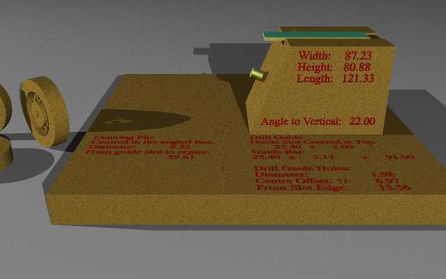
Drill Guide & Axle Pin Geometry
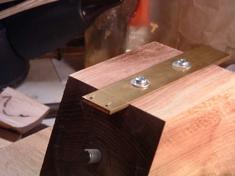
Drill guide
- Do not use a bar wider than 1", it will hide some of the alignment marks on the angled face.
- Mark the centre line along the bar's length.
- Mark a perpendicular 3 mm.(0.118") from the end.
- Mark 7mm.(0.276") to each side of centre on this perpendicular
- Centre punch these marks and drill with 5/64" bit.
- Put distinguishing marks beside the holes. In the picture below you see one centre punch dot beside the left hand hole and two dots beside the other.
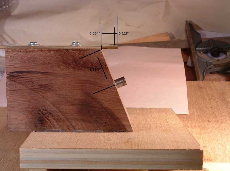
- Mark another perpendicular 16.5 mm.(0.650") from the same end, or 13.5 mm.(0.534") from the holes.
- Extend the second perpendicular down the sides of the bar. This is the overhang alignment mark.
- Drill two oversized holes (for wiggle room) along the centre line for fastening the strip to the block.
Detail of Drill Guide
Spoke Hole Alignment Marks
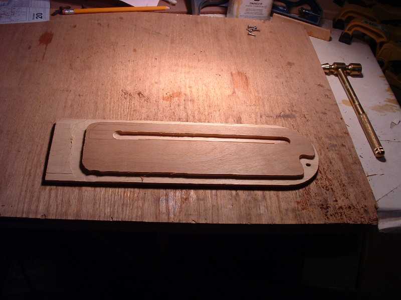
Block
- I used a solid block of my black walnut 3 1/2" wide, 3 1/8" high 4 3/4" long. A light coloured wood would be better, it is hard to see the alignment markings on such a dark wood. I used my wife's dressmaker's chalk to fill the marks with white.
- Angle cut one end at 22 degrees from the vertical.
- Router a slot in the centre of the top to fit your drill guide.
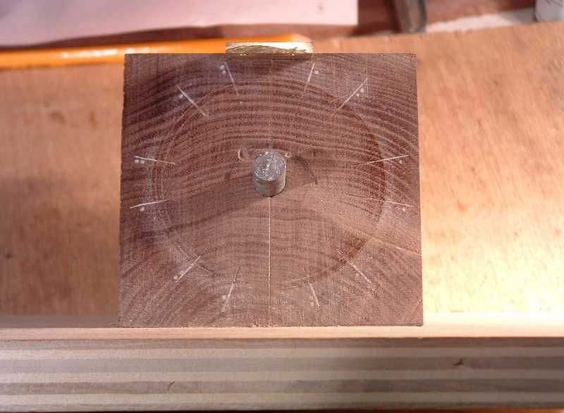
- Put wheel disk alignment markings on the angled face:
- Mark a centre line on the angled face aligned with the centre line of the drill guide slot.
- Measure and mark a point 1.560" down this line from the bottom of the guide slot. This is the centre point where the wheel will be held.
- Mark a circle with 1/2" radius around the centre point. This is the hub circle.
- Mark another circle with 1.334" radius. This the wheel disk circle.
- Facing the angled face draw a line from the right edge of the guide slot through the centre point out past the wheel disk circle on the bottom left side.
- Draw two more lines through the centre at 60 degrees to either side of the first.
- Mark both ends of these lines with a single dot, they are the alignment marks for drilling through the one dot drill guide hole.
- Measure and draw a line across the circle angled 21.5 degrees clockwise from the first line.
- Draw two more lines at 60 degrees to either side of this last line.
- Mark both ends of these last three lines with two dots. They are the alignment marks for drilling through the two dot hole in the guide.
- To make my marks visible I used a V chisel to cut the ends of the lines and rubbed dressmaker's chalk into the grooves
- Assembly
- Drill a perpendicular hole in the centre point marked on the angled face of a size to take the lag bolt.
- Screw in the lag bolt and saw off its head. File off the burr from the saw cut.
- Position the drill guide in its slot with the overhang alignment mark aligned with the end of the bottom of the slot. Mark the screw hole positions.
- Remove the guide and drill holes for the screws.
- Screw down the guide making sure the overhang alignment mark stays at the edge of the bottom of the guide slot.
- Glue the assembled block onto the base.
Drilling First One Dot Hole on Disk Side 2
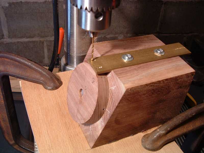
Wheel clamp
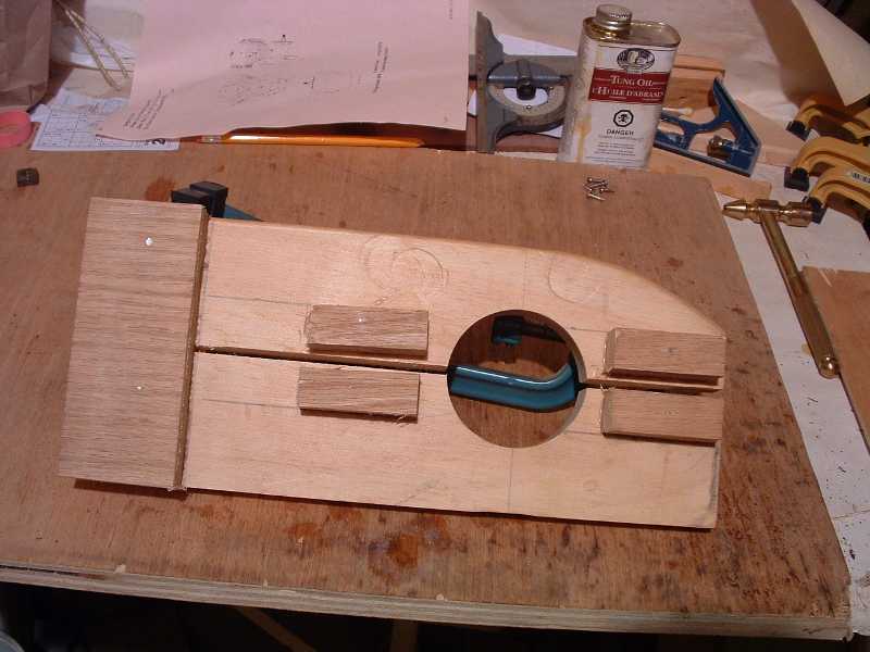
Since the same operations are repeated on each wheel I came up with this rig so I would only have to align it on centre once for the first wheel disk then the rest would automatically be centred. The hole is cut with the adjustable circle and hole cutter to match the diameter of the wheel disks. The kerf of the 12" blade for my table saw is just over 1/8" wide, providing plenty of squeeze room. The re-enforcing block at the far end and the clamping blocks are glued and screwed securely.
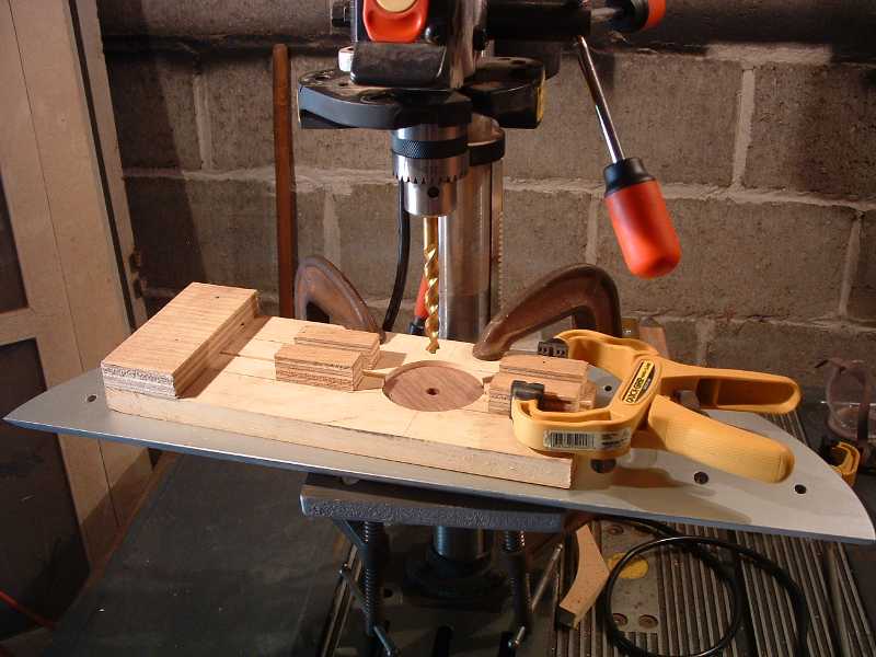
The two C clamps at the back hold it in position on the table, leaving the front loose so the squeeze clamp can pinch the wheel disk in the hole.
For the first job, drilling the 3/8" axle hole, you might need a pair of snap ring pliers to lift the disk out of the clamp.
Addendum:
Even after a half hour of aligning this thing for the hub and rim cutting, I got those cuts way off centre. I managed to cover up the eccentricity while turning the tire profile. But here is how to get everything centred each time.
- Cut three squares a little wider than the wheel diameter from the 1 by material used to make the wheel clamp.
- Make 1/8" deep circle cuts in the centre of each of these squares with the adjustable circle cutter set at the wheel radius, 1.33".
- Drill through the centre of each of them with one of the different tools you will be using on the wheels, a 3/8" drill, a 1" plug cutter, and a 1 3/4" sawtooth Forstner bit.
- Repeat above steps until you have perfectly centred examples of each.
- Use the router to take out the material outside of the circle so you have plugs that will fit into the wheel hole in the clamp. Trim the sides as needed to fit beside the clamping blocks.
In use, insert the plug for the tool you are about to use into the wheel clamp hole. Align the wheel clamp so the tool fits the hole then clamp the clamp to the drill press table. Then just put the plug on top of each wheel disk in turn, twist it clockwise until stopped against the clamping block, to prevent it spinning. Fit the bit into the hole before turning on the drill and bore out a perfectly centred hole each time.